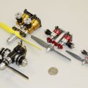
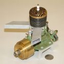
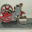
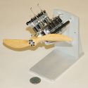
.040 Opposed 2-Cylinder, 2-Cycle Aero Engine
Craftsman: John Swartzwelder
Knapp Collection #: 206
Catalog #: 2008.16.49
Contributor: Paul Knapp
John Swartzwelder fabricated several small multi-cylinder aircraft engines from commercially available Cox .049, .020, and .010 cc model airplane engines.
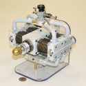
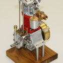
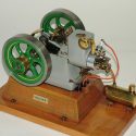
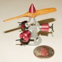
.098 Opposed 2-Cylinder, 2-Cycle Aero Engine
Craftsman: John Swartzwelder
Knapp Collection #: 205
Catalog #: 2008.16.47
Contributor: Paul Knapp
John Swartzwelder fabricated several small multi-cylinder aircraft engines from commercially available Cox .049, .020, and .010 cc model airplane engines.
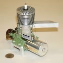
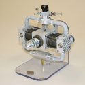
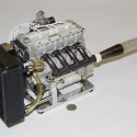
.098 Vertical 2-Cylinder, 2-Cycle Aero Engine
Craftsman: John Swartzwelder
Knapp Collection #: 204
Catalog #: 2008.16.46
Contributor: Paul Knapp
John Swartzwelder fabricated several small multi-cylinder aircraft engines from commercially available Cox .049, .020, and .010 cc model airplane engines.
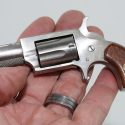
.22 Caliber Revolver
Craftsman: Birk Petersen
Catalog #: 2016.15.19
Donor: Mark Petersen
The pistol was “decommissioned” so that it will not actually fire .22 cartridges, although it duplicates all functions of the original.

’32 Ford Coupe Tether Car
Craftsman: Marshall Ziegert
Catalog #: 2016.8.14
Contributor: 419
This ’32 Ford tether car measures about 7 inches wide, 4.25 inches high, 13 inches long, and weighs 6.25 pounds.

“Cyclone Racer” Wooden Roller Coaster Model
Craftsman: Richard Docken
Catalog #: 2014.2.1
Donor: Donald Woods
Richard Docken’s wooden HO scale model of the Cyclone Racer roller coaster. The model is about 6-feet long and made from thousands of pieces of balsa wood.
“Dominator” Model Aircraft Engine
Craftsman: Noel Jensen
Knapp Collection #: 85
Catalog #: 2008.10.26
Contributor: Paul Knapp
To achieve more power, Noel Jensen added two more cylinders and produced this flat 4-cylinder opposed engine dubbed the “Dominator.”
“Green Dragon” Model Airplane Engine
Craftsman: John Nuovo
Knapp Collection #: 132
Catalog #: 2008.10.37
Contributor: Paul Knapp
The Green Dragon burns methanol with castor oil mixed in for lubrication on spark ignition. The engine is 7″-long, 5″-wide, and 6″-high.
“Green Dragon” Model Automobile Engine
Craftsman: John Nuovo
Knapp Collection #: 133
Catalog #: 2008.10.38
Contributor: Paul Knapp
This two-cycle, air-cooled Green Dragon automobile engine was named for its green crackle paint finish. This engine is 7″-long, 5″-wide, and 6″-high.
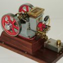
“Hired Man” Hit N’ Miss Engine
Craftsman: Mr. Hallock
Catalog #: 2011.4.3
Donor: Les Cade
This “Hired Man” hit n’ miss engine features a governor in the center of one of the 6″ flywheels, and spark is provided by a Model T Ford ignition coil.
“KEN” Single-Cylinder, Air-Cooled Marine Engine
Craftsman: Dick Pretel
Knapp Collection #: 181
Catalog #: 2008.16.32
Contributor: Paul Knapp
From approximately six sets of castings made by Ken Brennerman in the mid 1930s, this is the only known surviving engine.
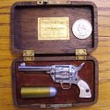
“Little .45” Miniature Colt .45 Pistol
Craftsman: American Miniature Gun & Cartridge Co.
Catalog #: 2008.14.1
Donor: Bob Mellman
The “Little .45” is a miniature replica of the famous Colt .45 Peacemaker, and actually fires small percussion cap-like blanks.
“Little Brother” Hit N’ Miss Engine
Craftsman: Mr. Hallock
Catalog #: 2011.4.2
Donor: Les Cade
This “Little Brother” hit n’ miss engine features a governor in the center of one of the flywheels, and spark is provided by a Model T Ford ignition coil.
“Little Brother” Hit N’ Miss Engine
Craftsman: Mr. Hallock
Catalog #: 2011.4.6
Donor: Les Cade
This water-cooled “Little Brother” hit n’ miss engine features a governor in the center of one of the 4.5″ flywheels.
“Little Dominator” Model Aircraft Engine
Craftsman: Noel Jensen
Knapp Collection #: 84
Catalog #: 2008.10.25
Contributor: Paul Knapp
A rotary valve, twin-cylinder, air-cooled engine named “Little Dominator.” The 1″-bore and 1.1″-stroke engine turns a 16/6 propeller at 6,000 rpm.
“Maxse T-Seven” 7-Cylinder Radial Model Airplane Engine
Craftsman: Maxse Tayler
Knapp Collection #: 126
Catalog #: 2008.10.36
Contributor: Paul Knapp
Maxse Tayler used the piston and cylinder assemblies from the commercially manufactured Saito 120 model airplane engines to build this 7-cylinder radial.
“Micro Cirrus” V8 Engine
Craftsman: Profi M. E.
Knapp Collection #: 112
Catalog #: 2008.10.31
Contributor: Paul Knapp
This 1/12 scale “Micro Cirrus” engine runs on methanol with glow ignition, and is among the smallest multi-cylinder 4-cycle engines in the world.
“Rasant MK III” Diesel Radial Model Airplane Engine
Craftsman: Ron Valentine
Knapp Collection #: 135
Catalog #: 2008.10.39
Contributor: Paul Knapp
This “Rasant MKIII” Diesel engine operates like an inline engine. It is 2.5″-long, 3″-wide, and 2″-high.
“Root Special” DOHC 4-Cylinder Racing Engine
Craftsman: Lee Root
Knapp Collection #: 104
Catalog #: 2009.9.17
Contributor: Paul Knapp
The “Root Special” is machined entirely from 7075 aluminum bar stock and utilizes no castings. The aluminum parts were clear anodized to produce the color and finish.
Showing 20 of 1298 exhibits.