Gathering a Lifetime of Knowledge and Skill to Build the Ultimate USS Monitor Steam Engine
Joe Martin Foundation Craftsman of the Year Award Winner for 2009
Introduction
Being the son of an automotive mechanic tends to result in exposure to all kinds of mechanisms from a young age. Having older brothers who were deeply into model airplanes helps as well. Richard Carlstedt had both, and perhaps unsurprisingly, he built his first model airplane at the age of 5. Making the plane from balsa wood and nails meant his model couldn’t compete with his brothers’ U-control, gas powered planes—but it was a start.
Determination to Do a Better Job Starts Early
Fast forwarding to the age of nine, Rich built six “Comet” kits of a Spad—a World War I biplane fighter. Each stick and paper model was better than the last, and rubber-powered flight improved as his skills were honed. However, catching up to his older brothers, who were now flying scale, speed, and carrier planes, was still a long way off. Richard learned that failure was unacceptable, and continued to improve his skills until he achieved success.
For Richard, building aircraft was such a challenge that he wanted to be an aeronautical engineer at the age of twelve. However, before his dreams of engineering would come around, a unique thing happened. Richard read a book about the Civil War battle of Hampton Roads, and became hooked on the USS Monitor as a result. He built a powered model of that ship at the age of ten or eleven, never realizing that its engine would come to occupy years of his life later on.
Training in Engineering and Experience in Machining
Now, with a total focus on engineering Richard attended Tilden Technical High School in Chicago. At Tilden, he could get a full pre-engineering technical education. During that time, Richard continued building model aircraft. During his senior year in high school, he started working at Ford Aircraft as an apprentice machinist to make money for college. The machining skills that Richard learned there would serve as the foundation on which he would continually improve throughout his life.
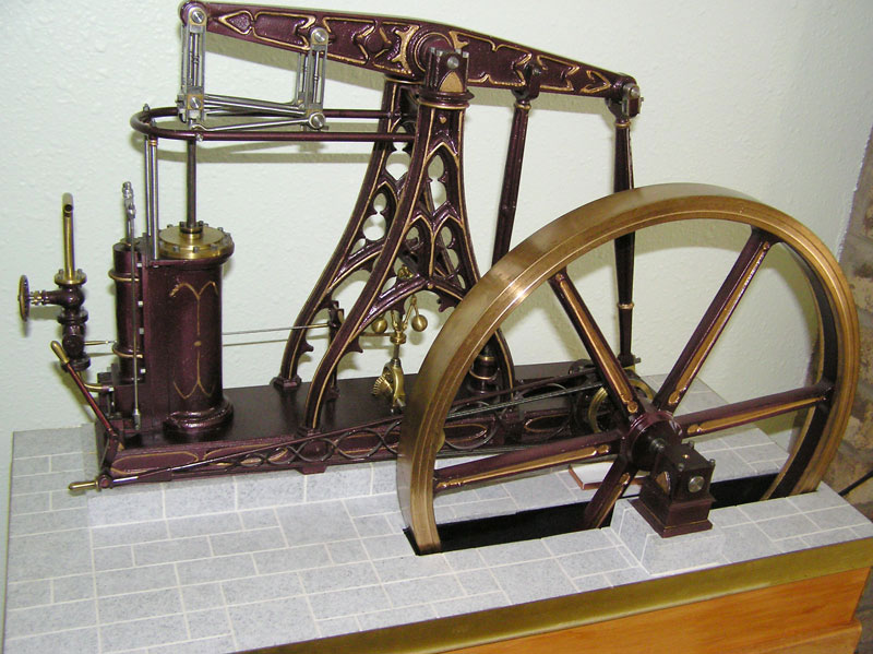
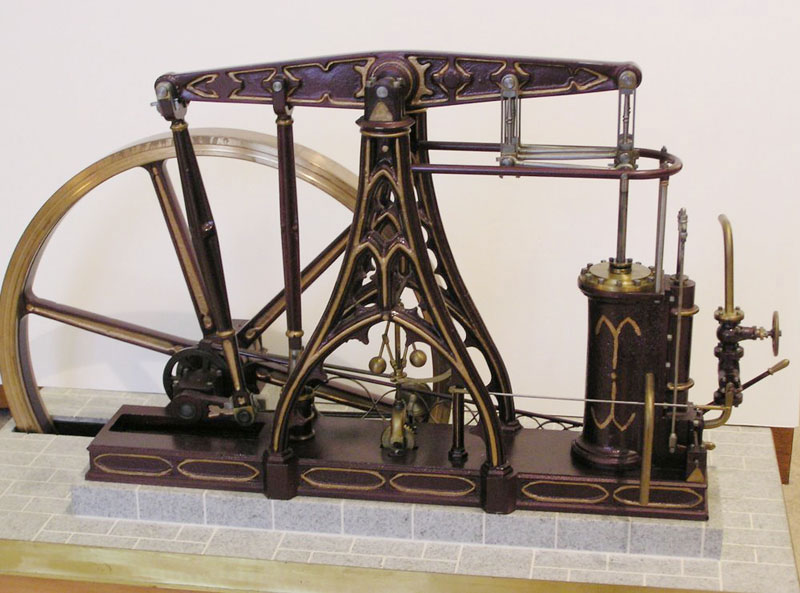
One of Richard’s creations, a model French beam steam engine from 1820. The 15″ flywheel was cast from a pattern made by a friend. It was built to a scale of .94″ = 1 foot.
Eventually, Richard entered the University of Illinois as an aeronautical engineering student. However, he quickly switched to mechanical engineering when a close friend told him he would never see the wind tunnel, or advanced research, because he wasn’t attending MIT or Cal Poly. Having no money certainly didn’t help either. Ultimately, Richard dropped out of college, got married, and went to work in construction. In the meantime, he was now flying radio control, and was the first RC flyer in Chicago during the 1950’s to have twin channel full proportional control. He had built his own radio and servos. Gas tubes really do work! Those were still the days of rubber band escapements or reed and servos (bang/bang).
Around the same time, Richard’s first metal engine work began as he made a custom exhaust restrictor on a Cameron 19 to facilitate low speed RC flying. However, hobbies would take a back seat as he started a family and continued to work. Richard went back to the metal working trades, and worked his way up from mechanic/machinist into management. During this time he continued to attend night school with aspirations of a degree.
Initial Foray Into Engine Making
In 1971, while on assignment in Canada, Richard became friends with two live steam fanatics who introduced him to the world of engine building. He started his shop with an Atlas lathe, an Atlas mill, and a Brown & Sharpe surface grinder. Richard joined the Ontario Sun Parlor Lines steam railroad club, and built his first steam engine—a Stuart Turner 7.
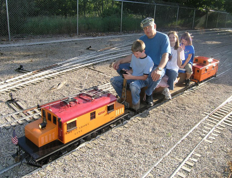
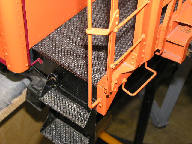
Richard taking his nieces and nephew for a ride behind his steeple cab electric, at the White Creek Railroad track in Grand Rapids, Michigan. The engine is all steel. The wheels were cast from patterns built by Rich, and the caboose is metal clad over wood. More details of the caboose are shown below.
Later on in 1973, Richard’s friend Norm Mclellan asked him for help on a project. He ended up building three fully retracting and rotating landing gears for Norm’s 9-pound Shrike twin-engine plane. Such air-powered units were not on the market, or even known at the time, and Norm went on to win the Canadian Nationals. Rich had made the design as a kid twenty years earlier while flying carrier U-kie. Only now he was able to do a much better job with a machine shop in the basement.
While still in Canada, an article in National Geographic magazine came to Richard’s attention. The article noted that the USS Monitor—the civil war era ship that Richard had read about as a child—was found off of Cape Hatteras. His early interest in the ship was rekindled, and Richard continued to follow that story through the years. Returning to the United States after four years allowed Rich to join the Chicago Model Engineers. There he would learn from, and follow in the footsteps of some of the great modelers in that club—like Emery Ohlenkamp and Roy Ozuf.
Rich continued to develop his machining skills, and was especially assisted by his father-in-law who was a retired toolmaker. Richard noted that his father-in-law was one of the most diversified old-time machinists he had ever met. Rich was very fortunate to learn his shortcuts and machining approaches. Eventually, Rich left Chicago and moved to Northern California to work in several positions. His career had now developed into manufacturing engineering, with a focus on machinery and assemblies.
After ten years in that capacity (a requirement), he traveled to Detroit where the Society of Manufacturing Engineers (SME) was based. Once there, Richard would successfully complete the SME’s intensive testing program to receive full certification and credentials as a manufacturing engineer. He continued working with metal dies and machinery, and was eventually transferred to Wisconsin.
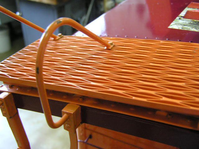
Close-up shots of some features on Richard’s South Shore Line locomotive. The left picture shows the ladder and rungs, while the right picture shows the roof safety walk.
Model Work
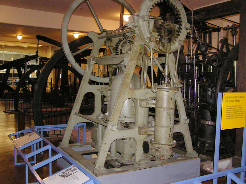
During his time in Canada, aside from starting to build models, Richard visited the Henry Ford Museum in Dearborn, Michigan in 1972. He was struck by the complexity of the Matthew Murray Hypocycloidal Steam Pumping Engine, and the revolutionary aspects of its construction. Richard took a hundred photos of the engine, and made copious notes on all of its dimensions.
While on a trip to England in 1977, Rich found a patent model of the USS Monitor engine on display at the British Science Museum. Alas, his boyhood interest was renewed, and Rich promised himself that he would attempt to build the engine when he retired.
Richard’s busy work schedule was only interrupted when he got into 1-1/2” scale live steam railroad activities. He scratch built a “steeple cab” electric engine using all steel construction, and made all his own parts except for the controller. His South Shore caboose, also scratch built, has some unusual features—such as steel safety walks on the roof made from street sweeper bristles. Additionally, all the handrails were made by forging them with a die that pre-formed the steel mounting ends, and perforated them at 1500° F.
Medical Restrictions Force a Transition to Smaller and Lighter Projects
As Richard got older, medical restrictions prevented him from lifting heavy weights, so he drifted a bit from large scale railroading. In lieu of that, he decided to focus on table models of historic engines, and to build them in great detail. Rich started with some patterns built and loaned to him by his friend, John Grant. John had made them from a French mechanical book dating to the early 1800’s. Rich cast and machined all the parts in bronze at a college foundry, including an operating governor. The scale of this French beam engine model was 94-inches per foot, with a 15-inch flywheel.
After returning to the Midwest and building his dream shop, Rich finally had the opportunity to build using all the skills he had developed during his career. The long, cold winters were very pleasant inside a warm, friendly shop with lots of natural light.
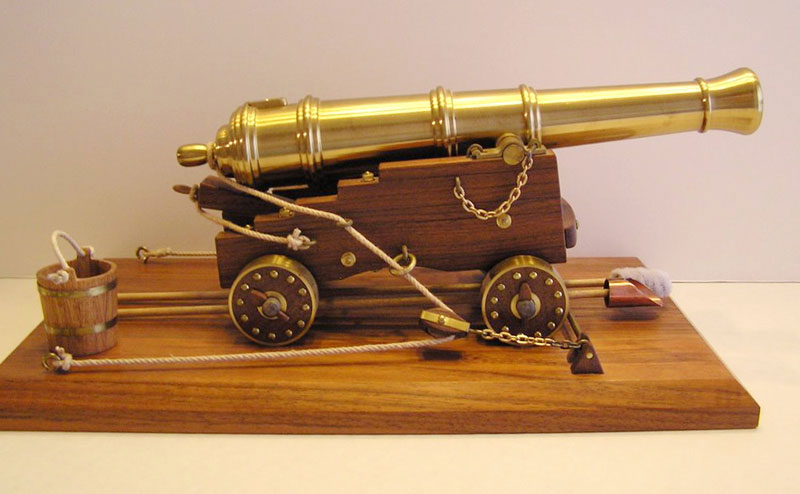
Richard was interested in artillery pieces, so he built a 1750’s era 24-pound fortress cannon for his first NAMES show in the early 90’s. At the time of this writing, Richard was expecting to do similar projects as he researched more about the French 75—the father of modern artillery, and a hopeful future project. The distinguishing marks of a fortress cannon are the metal clad wheels made to withstand cobblestone movement, as ship cannons had no such cladding.
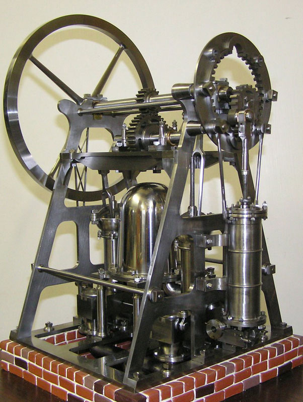
As Rich’s model work became more challenging, he started attending night school to learn AutoCAD and other skills. That included jewelry making (for model work), and lost wax casting (which he does not use for his models). Using his notes from years earlier in 1999, Richard returned to the Ford Museum and commenced modeling the 1806 Matthew Murray Hypocycloidal Pumping Engine in 1/8 scale.
A Model Built in the Memory of a Good Friend
The December that Richard began this project, his close friend Emery passed away. At that point, Rich was still working on his AutoCAD drawings for the Hypocycloidal engine. Rich noted that Emery was one of the finest builders he’d ever encountered.
So Rich decided to dedicate the construction of his model to Emery’s memory, and to maintain his friend’s high standards as a guideline. Emery loved cast iron, and he always mentioned to Rich that paint covers the beauty of iron. So Rich decided to build a model without paint.
Now, doing so required special work, and he had to make the parts without soldering them or else the lines would show. As a result, the entire engine was made from solid bar stock, and no castings were used. The parts were made with cast iron (meehanite and ductile) and steel. No plating, and no stainless was used—only the color of real iron at 1/8 scale. Accomplishing all of this became a real challenge.
All of the parts had to be functional, including the pumps, and doing so required the hand forging of many parts for an authentic look. Additionally, all fittings (screws) were fabricated to exact scale, and even the pressure angle of the gears matches that of the prototype. In order to match the original engine, which was made in 1806, all of the nuts and bolts had square heads. This was because a milling machine to make hex bolts wasn’t patented until 1830, and commercial hex bolts were not readily available until about 15 years later. Parts were forged to match the design as closely as possible.
Among these parts was the fancy valve eccentric rod, and .020” rivets to hold the lattice iron. The forging allowed the steel to be split into two legs. The steel would go from rectangular to .120” round, and then reduced to .06” for threading 0-80. The pump “fork” rod close-up shows the forged offset eyes within the fork—something that is extremely difficult with conventional machining.
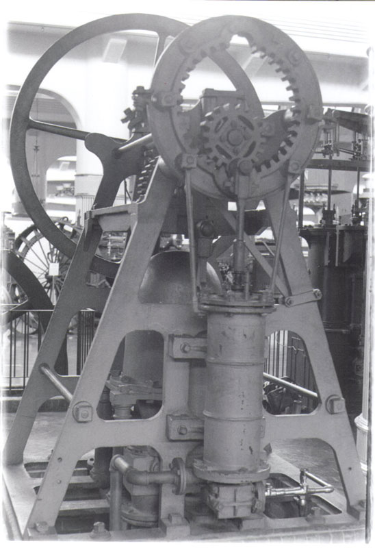
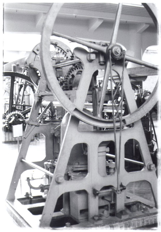
More photos of the Hypocycloidal Pumping Engine from the Ford Museum in Michigan, in 1972. This is the real engine from which Richard’s model was derived.
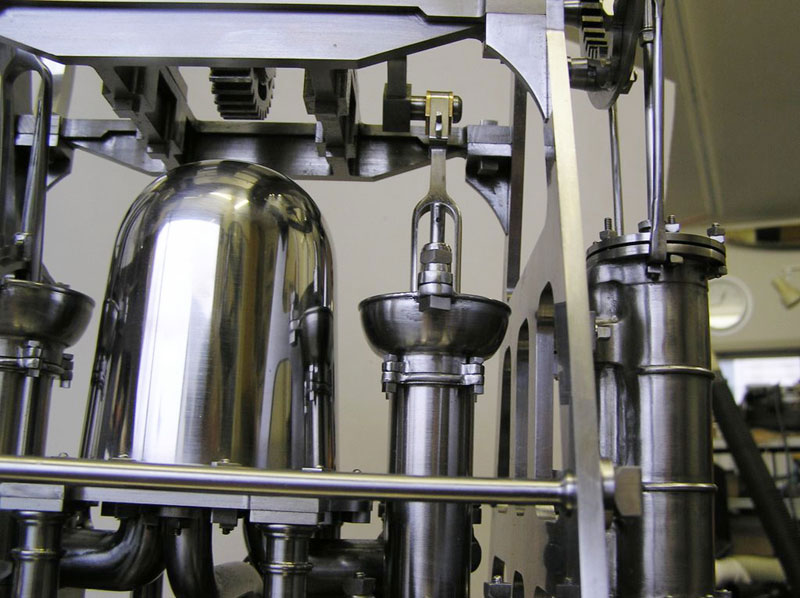
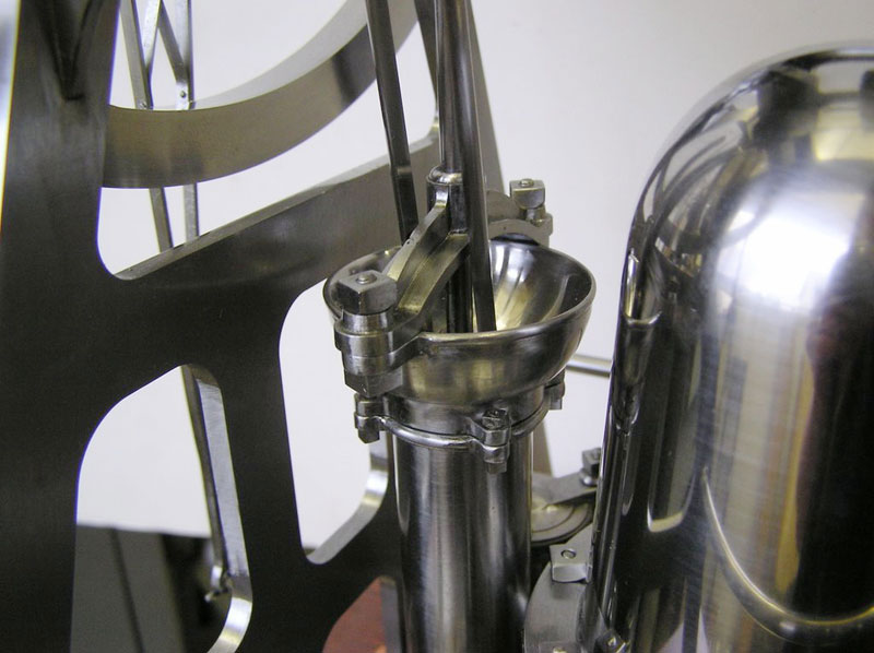
Now, making parts without seams or soldering required new machining techniques. The water pump cylinder and bowl close-up shows four beads, and four ears. If you study the water filling bowls pictured below—which were also made from solid stock—you can notice beading around the bowl lip and mating surface to the pump cylinder.
This work was done via “rotary shaping” of the part. The bowl was mounted in the lathe, and the form tool engaged on the surface. The chuck was hand-turned 160 degrees (not exact), the tool retracted, and the chuck returned to start over. This meant four operations (two one way, and then two the other direction) to do the two beads on one bowl alone. The water pump cylinder took eight setups!
This rotary shaping operation was a real necessity on the steam cylinder. Note that the cylinder has a cross-sectional shape like a number 8—with the steam passage in the rear, and the larger main piston bore in front. This design prevents turning the OD in the lathe, and is further complicated by having the legs stick out (because of no silver soldering). The cylinder took fifty hours of hand turning in the lathe, with a form tool turning the chuck about 260 degrees at a time to get the exact appearance of a casting—even though it was made from solid.
The photos above show the pump bowl beading, and close-ups of the pump bowl itself. These proved difficult and time-consuming to machine, but Rich used his skills to prove that good craftsmen find a way!
The USS Monitor Project Returns
In 1997, Rich heard that the US Navy was starting to recover USS Monitor parts, and he wanted to build the engine accurately. He started extensive research, as no drawings of the engine were available. Thankfully, Ray Hasbrouck, who Rich knew from NAMES (North American Model Engineering Society), kindly pointed him in a starting direction. Rich spent time at every known source he could find for information on the Monitor. Those places included: the Smithsonian, the National Archives, the US Navy Historical Records, the British Science Museum, and the Mariners’ Museum.
Rich slowly pulled together all of this information about the storied warship, along with John Ericsson’s patent history. This allowed him to piece together all of the necessary information to build an accurate operational model of the USS Monitor steam engine—in every detail. First, however, he had to draw all the parts in AutoCAD in full size. Then he could reduce them to model size in the scale he had chosen—1/16.
A Year Lost to Failed Castings
For this project, like the Hypocycloidal engine, no castings were used. Rich said, “I tried, but the complexity prevented me from getting good quality. I lost 12 months just trying to cast the main steam induction pipe, and the 2 cutoff chest covers—three parts and over 68 failed castings!” His persistence was learned at a young age, making the six Spad airplane models until he got them right. The persistence paid off again when he resorted to modeling the parts from solid stock, and gave up on the casting process.
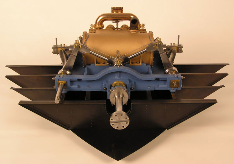
In order to match the prototype, close communication with the Mariners’ Museum was necessary. The assistance of the staff helped make this project a successful one. The engine itself is commonly known as John Ericsson’s Vibrating Lever Engine. However, it was really also a Half Trunk Engine in order for Ericsson to shoehorn the engine into the small space it occupied on board the ship.
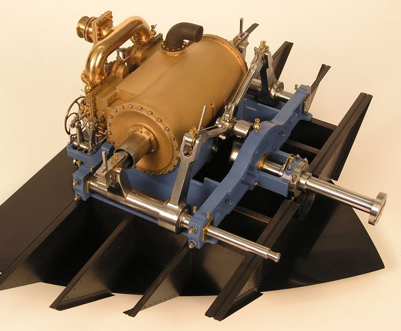
A stern view of the Monitor engine. You can see from the frame members underneath that the engine was a tight fit in its compartment.
Since there were no complete drawings or data published, Rich wrote and published his own book about the engine. When speaking about the book, Richard said, “Realizing the importance of the information I had gained, I decided to reproduce these images and dimensions in a current drawing format. It took three years, but I finished drawing all the parts and components used on this magnificent piece of engineering.” Four copies of the 309 page book were produced, and two were given to the Mariners’ Museum in Virginia.
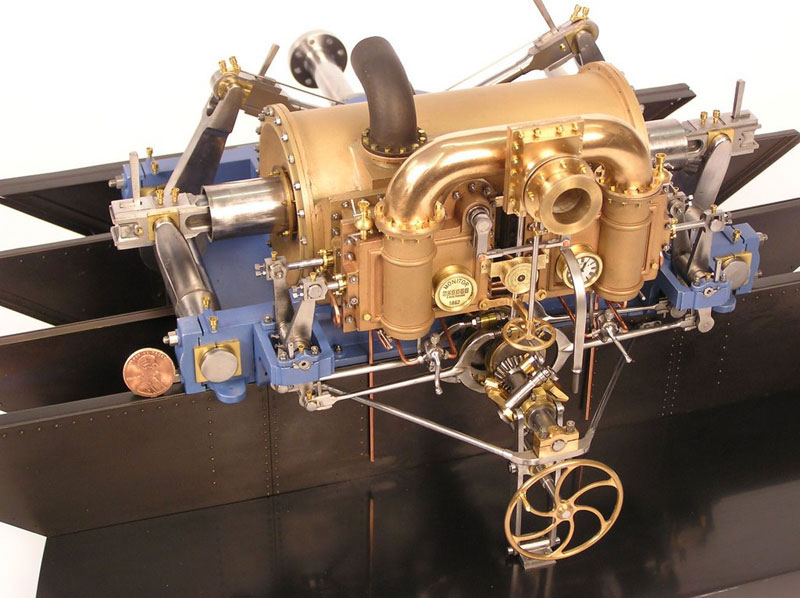
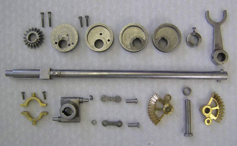
The model has scale operating valves, including throttle and cutoff. The 3-way valves used for recording steam events are functional, and they include 1/16” flared copper lines and fittings. Bearings are both bronze and Babbitt in their respective places. The matte finished bronze represents cast iron on the real engine. Rich couldn’t get a foundry to pour the iron, so he used bronze.
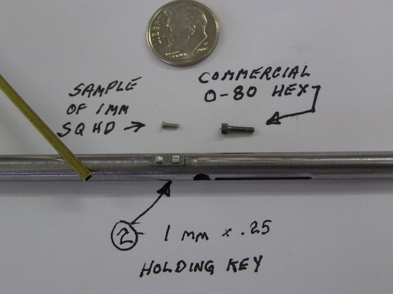
All the fittings are to scale, including the numerous .030” x .030” x .078” keys. All told, the research and construction took six years of work. Because this engine project was a self-inspired research project, Richard wanted all parts—visible or hidden—to be true to the originals. Therefore, all internal components are as accurately reproduced as the external parts.
Now, the three instruments on the face of the engine are the only non-functional pieces of the model. The steam gauge is about 3/8” in diameter, and the lettering that says “American Steam Gauge—Boston” is .018” tall. Rich engraved it himself, along with the clock and the engine register faces. He was actually in search of a round mechanical clock, about 1/2” in diameter, to replace the non-functional one.
Some of these small parts would have had to be remade if the Monitor engine hadn’t run on the first attempt. Richard was relieved that the first time really was the charm!
The engine was first run on February 12, 2008. It served as a tribute on the birthday of his good friend Tom, who had passed five years earlier. Richard was very relieved that it worked perfectly the first time, to his own amazement! He went on to say that, “With all the parts, valves, and fittings assembled without any method of pre-trial testing, and working with what I believed was the proper timing—including all the friction of new parts—I was amazed and pleased that it ran the first time. To change the valve timing, I would have needed to make a whole new reversing shaft, and completely disassemble the lower half of the engine. The shaft has a key, which is 50° offset from the crank follower, as you can see [in the pictures of the engine above]. To change timing means a new shaft with the tapered rectangular broached hole moved to a new position…a change I did not have to make.”
There is a short video of the engine in action, running smoothly. For those interested in learning more about the history of the USS Monitor, there is a fine exhibit at the Mariners’ Museum in Newport News, VA.
Richard’s Shop
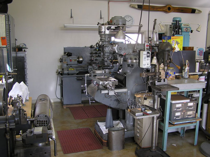
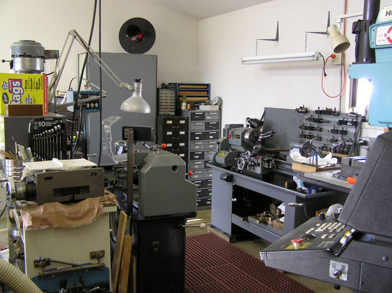
When it comes to his shop, Rich likes it to be open with lots of light. In California, he learned the benefit of a shop that takes advantage of energy saving sunlight. The shop has two benches, two mills, two lathes, and two drill presses. Having the duplicates really comes in handy when he can leave a job in one to work on another. This started when his father-in-law lived with them, and continued as Rich taught several fellow model builders how to machine in his shop.
The lathes in Richard’s shop are a 10” Oxford, and a 12” Atlas-Clausing. His mills include a 1943 Bridgeport, and a 1989 Hurco 2-1/2 axis. Rich also has a Rhodes shaper to round out the tools. Along with that equipment, he makes many special tools like broaches, form tools, and cutters using broken end mills or other shop cast-offs. Rich also has over 500 files, which is a necessity for the extensive handwork that he enjoys. The shop tools represent the sum of two lifetimes of craftsmanship—his father-in-law Charlie’s, and his own.
Richard Carlstedt Selected as the Joe Martin Foundation Craftsman of the Year for 2009
The Joe Martin Foundation is pleased to announce that Richard Carlstedt has been selected as the 13th winner of the Craftsman of the Year award. The selection was based not only on the quality of work that went into creating the model of the USS Monitor steam engine; but also the valuable historical research that led to its creation. Additionally, Richard has shared the vast knowledge he collected about this important historical artifact through the production of a book—which is now at the Mariners’ Museum in Virginia.
The research, combined with the uncompromising craftsmanship of each part of the engine—not to mention its resulting successful operation—have put this project and craftsman onto a higher tier. Richard poured a lifetime of engineering and metalworking skills into this project. It stands as a good example of how that determination and skill can lead to a project that attracts worldwide attention and acclaim. Richard has also contributed other significant pieces in the past that represent a significant lifetime body of work.
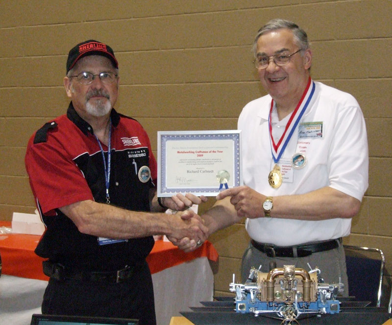
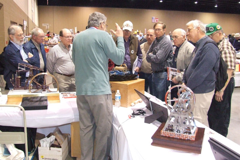
In the first photo, Craig Libuse (left) is representing the Joe Martin Foundation as he congratulates Richard for winning the 2009 Craftsman of the Year award. In second photo, Richard explains how the Monitor engine was built from only the minimal plans and information that could be found in historical archives around the world. Rich has uncovered a wealth of factual information, and explains it in a way that always attracts and holds an interested crowd.
The award was presented on April 18, 2009 at the North American Model Engineering Society Expo in Toledo, Ohio. Those attending the show were able to come by the Joe Martin Foundation booth to meet Richard, and to examine his work in person. Richard also brought some free color prints to give away, showcasing the USS Monitor engine and his other work.
Articles About Richard Carlstedt
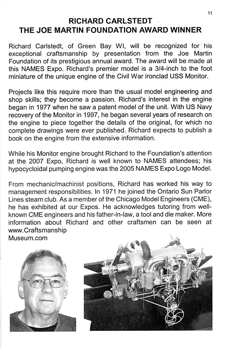
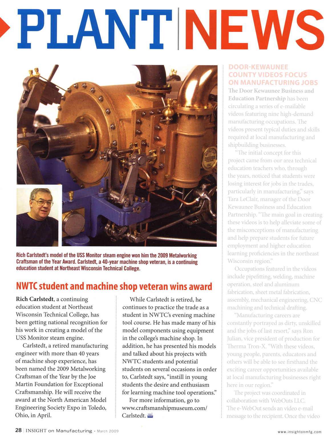
Several publications were kind enough to feature Richard and his work with a mention of his award from the foundation. Here are a couple of references (click on images to enlarge):
An article from the program for the 2009 North American Model Engineering Society Expo in Toledo, Ohio.
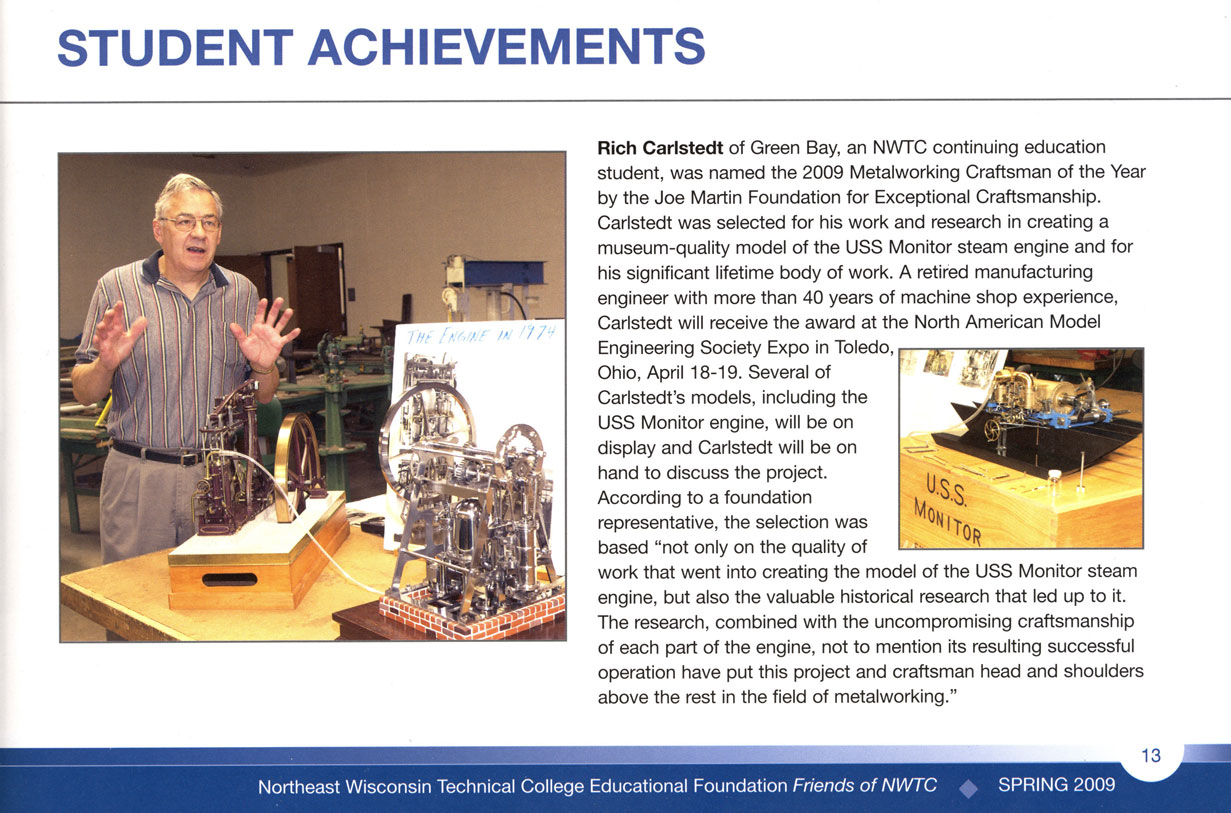
An article from Friends of NWTC, Spring 2009.
Additionally, The Home Shop Machinist magazine of May/June 2009 devoted two pages, and some nice photos, to highlight Richard’s accomplishments.
View more photos and details about Richard’s impressive projects.

